+86 18652221058
- Chinese
- French
- German
- Portuguese
- Spanish
- Russian
- Japanese
- Korean
- Arabic
- Irish
- Greek
- Turkish
- Italian
- Danish
- Romanian
- Indonesian
- Czech
- Afrikaans
- Swedish
- Polish
- Basque
- Catalan
- Esperanto
- Hindi
- Lao
- Albanian
- Amharic
- Armenian
- Azerbaijani
- Belarusian
- Bengali
- Bosnian
- Bulgarian
- Cebuano
- Chichewa
- Corsican
- Croatian
- Dutch
- Estonian
- Filipino
- Finnish
- Frisian
- Galician
- Georgian
- Gujarati
- Haitian
- Hausa
- Hawaiian
- Hebrew
- Hmong
- Hungarian
- Icelandic
- Igbo
- Javanese
- Kannada
- Kazakh
- Khmer
- Kurdish
- Kyrgyz
- Latin
- Latvian
- Lithuanian
- Luxembou..
- Macedonian
- Malagasy
- Malay
- Malayalam
- Maltese
- Maori
- Marathi
- Mongolian
- Burmese
- Nepali
- Norwegian
- Pashto
- Persian
- Punjabi
- Serbian
- Sesotho
- Sinhala
- Slovak
- Slovenian
- Somali
- Samoan
- Scots Gaelic
- Shona
- Sindhi
- Sundanese
- Swahili
- Tajik
- Tamil
- Telugu
- Thai
- Ukrainian
- Urdu
- Uzbek
- Vietnamese
- Welsh
- Xhosa
- Yiddish
- Yoruba
- Zulu
- Kinyarwanda
- Tatar
- Oriya
- Turkmen
- Uyghur

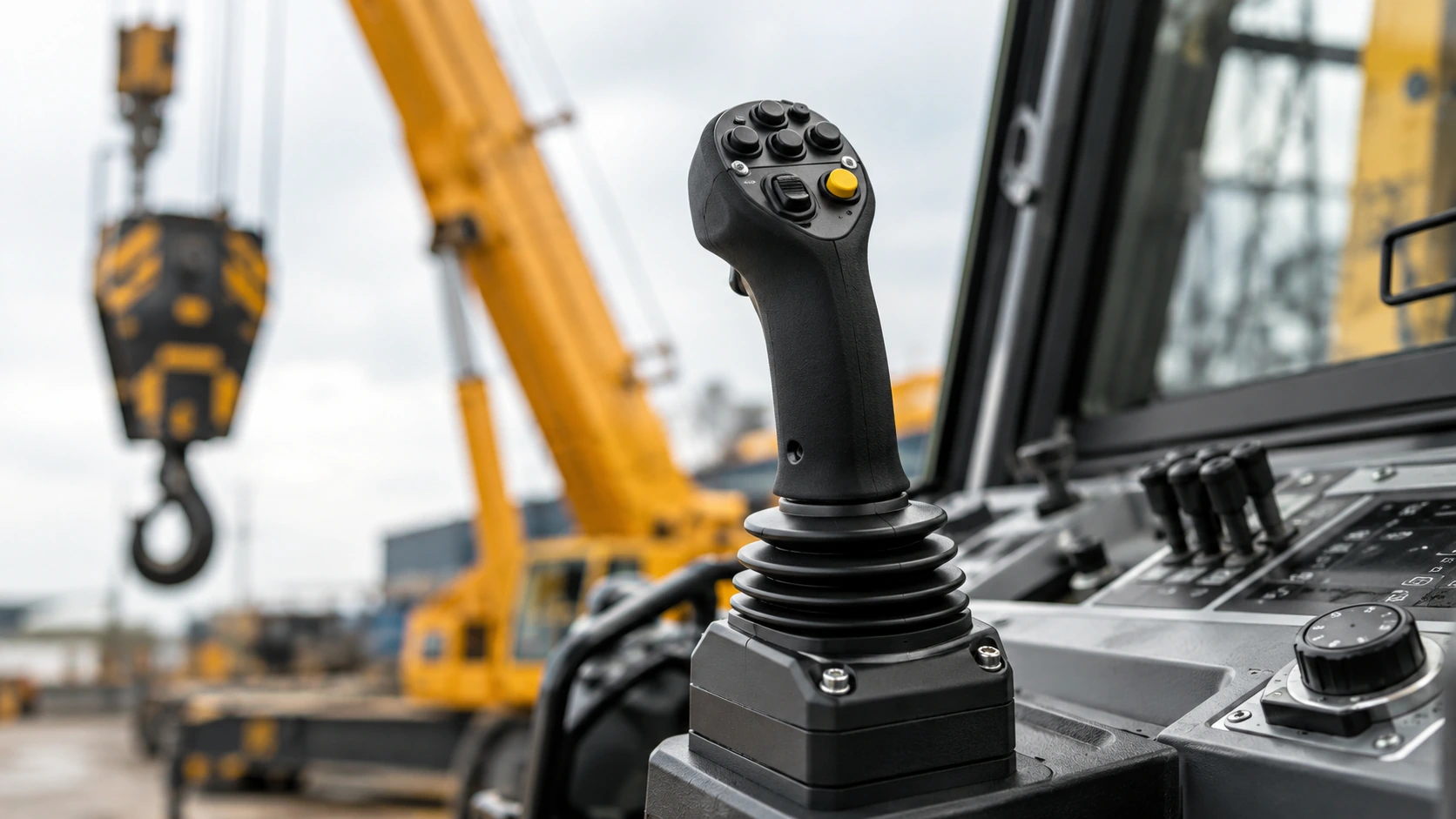
Direct answer: why does the wrong motion appear after replacement?
What wrong-function symptoms appear after joystick replacement?
Describe the motion precisely. “Joystick does not work” is too broad for diagnosis or an RFQ. Useful symptom descriptions include:
- Moving the lever forward commands the wrong crane function.
- The correct function moves in the opposite direction.
- One axis works while another is inactive.
- Motion begins before the lever leaves neutral.
- Speed changes abruptly or is uneven through the lever travel.
- The machine reports a fault only after the new handle is connected.
- A dead-man, enable or return-to-center function behaves differently.
The industrial joystick and control handle category shows several handle types, but visual similarity is not a compatibility decision. Each symptom should be linked to a specific axis, direction, operating condition and connector state.
| Observed symptom | Priority checks | Next controlled action |
|---|---|---|
| Wrong function moves | Axis assignment, connector pinout, controller input map | Compare original and replacement function maps |
| Correct function moves in reverse | Direction polarity, signal curve and parameter logic | Record readings by direction before changing settings |
| One axis is inactive | Supply, axis output, broken conductor and input channel | Isolate handle output from harness continuity |
| Uneven proportional motion | Signal technology, range, neutral, deadband and hydraulic response | Compare controlled signal readings through travel |
| Motion at neutral | Neutral voltage, offset, return mechanism and calibration | Stop operation and verify neutral safely |
| Fault code after connection | Pinout, supply, expected signal range and controller diagnostics | Capture the code and electrical evidence before reordering |
How can technicians isolate the handle from the controller, harness and hydraulic circuit?
Use a layer-by-layer diagnosis. First verify the replacement identity and installation. Then compare handle supply and output signals using the correct service information and qualified test equipment. Next check harness continuity, shorts, connector condition and pin location. Only after the input reaching the controller is understood should technicians investigate controller mapping, configuration or the downstream hydraulic and actuator response.
This order prevents two costly mistakes: replacing a second joystick when the harness is faulty, or changing controller parameters to compensate for an incompatible handle. It also avoids blaming electronics when the command signal is correct but the hydraulic circuit responds incorrectly.
Do the axis and direction assignments match the original handle?
A multi-axis joystick must map physical lever movement to the machine’s expected functions and directions. Document what forward, backward, left and right mean for the original handle, including any twist, buttons, triggers or enable switches. Then identify which replacement output corresponds to each movement.
A product such as the 3-axis Hall effect control handle may suit applications requiring multiple axes, but the number of axes does not prove that its direction map, connector or output matches the original crane. Do not swap pins experimentally while the crane has unrestricted movement.
Are output type, signal range and supply voltage compatible?
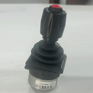
Industrial joysticks may use Hall-effect sensing, potentiometers, switches or combinations of outputs. Controllers can expect different voltage, current, resistance, PWM, switched or other signal behavior. A replacement that produces a valid signal of the wrong type or range may cause reversed, limited, saturated or faulted operation.
Compare the documented supply, ground, output technology, range and direction curve for every axis. For example, the EP/60B industrial joystick and a Hall-effect model represent different technical possibilities; neither should replace the other without interface confirmation.
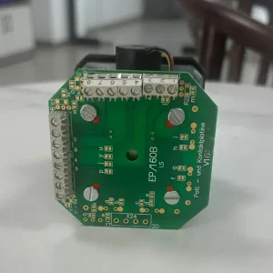
How do neutral position, deadband and return-to-center affect motion?
The controller needs to recognize a stable neutral condition. If the replacement neutral output falls outside the expected window, the machine may report a fault, refuse enable or command motion before the operator intends it. A deadband that is too wide can make the response feel delayed; one that is too narrow can make small offsets produce unwanted motion.
Check that the lever returns mechanically to center and that the signal returns consistently to the expected neutral region. Also verify any enable, dead-man or safety-related switch through the approved service process. Do not bypass these functions to make an incompatible replacement appear operational.
What is a safe post-replacement functional test sequence?
Testing must follow the crane manufacturer’s service instructions and be carried out by qualified personnel. Secure the work area, remove loads where required, limit possible motion, maintain emergency-stop readiness and avoid bypassing interlocks.
- Verify identity: Record original and replacement labels, mounting, connectors and part numbers.
- Inspect installation: Check connector seating, damaged pins, cable strain and return-to-center movement.
- Confirm power and neutral: Verify supply and stable neutral behavior using approved procedures.
- Check one axis at a time: Compare commanded direction with the expected function at the lowest practical controlled response.
- Observe proportional travel: Look for dead zones, jumps, saturation or failure to return to neutral.
- Capture diagnostics: Record fault codes, readings, axis map and any deviation.
- Release only after acceptance: Do not return the crane to service until the responsible technician confirms correct operation and safety behavior.
Which details should be compared before another joystick is ordered?
| RFQ field | Original joystick evidence | Replacement evidence required |
|---|---|---|
| Machine identity | Brand, model, serial and application | Confirmed application match |
| Joystick identity | Manufacturer and complete part number | Exact proposed model and revision |
| Mechanical format | Mounting, lever, axes, buttons and return | Dimensional and function comparison |
| Electrical interface | Supply, connector and pinout | Pin-by-pin compatibility |
| Signal behavior | Technology, range, neutral and direction curve | Documented or sample-tested match |
| Machine symptom | Axis, direction, fault code and readings | Supplier review and acceptance plan |
Include label, lever, mounting and connector photos; the function/direction map; supply voltage; output technology and range where documented; neutral and return symptoms; fault codes; signal readings; quantity; and a sample-first test requirement. This produces a more useful quotation than asking for a “same-looking crane joystick.”
Frequently asked questions
Does wrong motion prove that the new joystick is defective?
No. Axis mapping, pinout, signal compatibility, controller configuration, harness faults and hydraulic response can produce similar symptoms.
Can identical connectors have different pinouts?
Yes. Physical connector fit must be followed by a pin-by-pin electrical comparison.
Can a Hall-effect joystick replace a potentiometer joystick?
Only when the supply, output type, range, neutral behavior, pinout and controller expectations are confirmed compatible.
Why does the crane move before the lever leaves neutral?
The neutral output, deadband, return mechanism, calibration, wiring or controller interpretation may be incorrect. Stop operation and verify these fields safely.
Should technicians change controller parameters first?
No. Confirm the replacement handle identity, signal and harness before changing parameters that could hide the actual mismatch.
What is the safest first test after installation?
Begin with identity, installation, power and neutral checks, then test one axis at a time under controlled conditions and the manufacturer’s procedure.
What information helps a supplier identify the correct handle?
Machine and joystick identities, clear photos, axis/function map, supply, output and pinout data, symptoms, readings and the planned acceptance test are most useful.
Send diagnostic evidence for a replacement review
Provide the machine model and serial number, original joystick part number, label and connector photos, axis and direction map, supply voltage, output details where available, neutral behavior, fault codes, signal readings, quantity and safe sample-test requirement. Jiemanda can use this evidence to review available control-handle options and recommend the next quotation or verification step. Submit the details through the replacement handle inquiry page.
Feature Product
-
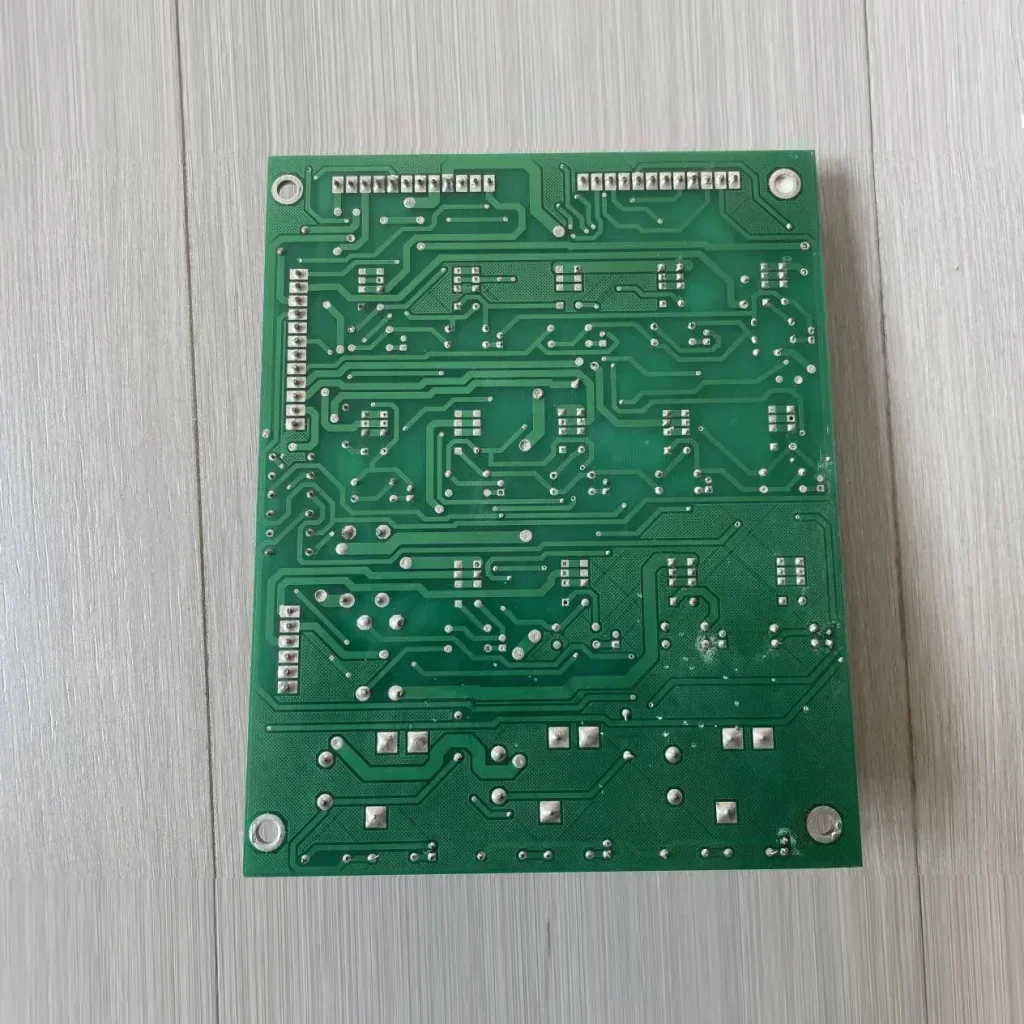 Zoomlion Original Power Control Board – ...
🔹 Core Functions Multi-circuit Power Distrib...
-
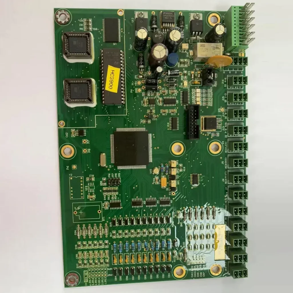 XCMG HC3900 Crane Upper Computer Mainboard
Key Selling Points OEM Direct Compatibility...
-
 Zoomlion Mobile Crane Load Moment Indicator (LM...
Product Overview This is an original equipment...