+86 18652221058
- English
- Chinese
- French
- German
- Portuguese
- Spanish
- Russian
- Japanese
- Korean
- Arabic
- Irish
- Greek
- Turkish
- Italian
- Danish
- Romanian
- Indonesian
- Czech
- Afrikaans
- Swedish
- Polish
- Catalan
- Esperanto
- Hindi
- Lao
- Albanian
- Amharic
- Armenian
- Azerbaijani
- Belarusian
- Bengali
- Bosnian
- Bulgarian
- Cebuano
- Chichewa
- Corsican
- Croatian
- Dutch
- Estonian
- Filipino
- Finnish
- Frisian
- Galician
- Georgian
- Gujarati
- Haitian
- Hausa
- Hawaiian
- Hebrew
- Hmong
- Hungarian
- Icelandic
- Igbo
- Javanese
- Kannada
- Kazakh
- Khmer
- Kurdish
- Kyrgyz
- Latin
- Latvian
- Lithuanian
- Luxembou..
- Macedonian
- Malagasy
- Malay
- Malayalam
- Maltese
- Maori
- Marathi
- Mongolian
- Burmese
- Nepali
- Norwegian
- Pashto
- Persian
- Punjabi
- Serbian
- Sesotho
- Sinhala
- Slovak
- Slovenian
- Somali
- Samoan
- Scots Gaelic
- Shona
- Sindhi
- Sundanese
- Swahili
- Tajik
- Tamil
- Telugu
- Thai
- Ukrainian
- Urdu
- Uzbek
- Vietnamese
- Welsh
- Xhosa
- Yiddish
- Yoruba
- Zulu
- Kinyarwanda
- Tatar
- Oriya
- Turkmen
- Uyghur

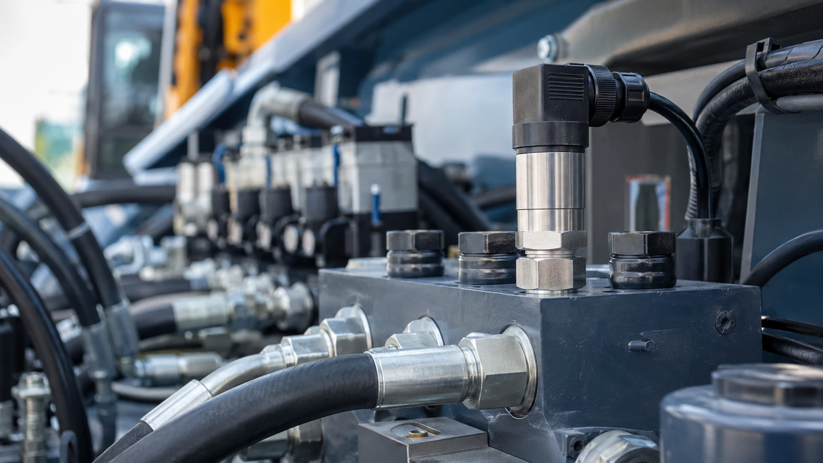
When comparing crane hydraulic control components, buyers should first identify what the target part actually does. A pressure transducer measures hydraulic pressure and sends data to a controller; it is not the complete hydraulic controller. Correct replacement therefore depends on pressure range, process connection, electrical connector, supply and signal interface, network protocol, message mapping, installation position, environmental duty and system calibration. A device marked 0–300 bar or CANopen is not automatically interchangeable with every sensor carrying the same words. The RFQ should map the hydraulic measurement point to the crane function, original part identity, mechanical port, electrical interface and control-system expectation. Compatibility must be confirmed across the complete chain: pressure source → transducer → wiring/network → controller → display or safety logic.
Separate the Pressure Transducer From the Hydraulic Controller
The controller makes decisions or issues commands according to its program. The transducer converts hydraulic pressure into a signal that the controller can use. Confusing these two parts creates an inaccurate RFQ and can direct the supplier toward the wrong product family.
Start by asking whether the failed component measures pressure, processes multiple inputs, drives an actuator, or performs more than one function. A cylindrical device threaded into a hydraulic line is commonly part of the sensing layer. A multi-connector electronic unit may be the controller, but appearance alone is not sufficient.
For pressure-input replacement, buyers can review the Hirschmann sensor category before moving to an exact model. This keeps product discovery aligned with the actual component.
Which Inputs Define Compatibility?
| Decision Variable | Buyer Must Provide | Why It Matters | Supplier Evidence |
| Measurement duty | Hydraulic function and measurement point | Defines what pressure is being monitored | Application match |
| Pressure range | System working and transient conditions | Wrong range can affect suitability or interpretation | Exact rated range |
| Process connection | Thread and sealing arrangement | Controls mechanical installation and leak integrity | Port specification |
| Electrical connector | Connector family, pin count and keying | Physical fit does not prove pin compatibility | Connector and pinout |
| Signal/protocol | CANopen or other required output | Controller must read the signal correctly | Interface specification |
| Network mapping | Node and application requirements | Protocol name alone is incomplete | Configuration status |
| Installation | Location, orientation and cable routing | Affects fit and serviceability | Dimensions and installation scope |
| Environment | Temperature, vibration, contamination and pressure dynamics | Defines field duty | Declared limits |
| Acceptance | Test and diagnostic requirement | Provides a release basis | Inspection/test record |
Why Must the Pressure Range Match the Real Circuit?
The nameplate range must be evaluated against the actual measurement point. Boom extension, luffing, lifting and stabilizer circuits may have different normal pressures and transient behavior. The buyer should identify the circuit, expected working range and any known pressure spikes from machine documentation or engineering review.
A higher range is not automatically safer. It may change the resolution or scaling expected by the controller. A lower or unsuitable range can create another mismatch. Do not select solely from the machine’s general hydraulic-system description; use the requirement at the sensor port.
Where the old reading is unreliable, avoid using that single reading as the only range evidence. Check the original part data, hydraulic schematic and machine documentation.
Mechanical Port and Sealing Must Be Verified Separately
The process connection determines whether the transducer can be installed without unsafe adapters or leaks. Confirm thread form, nominal size, sealing method, shoulder geometry, insertion depth, wrench clearance and orientation.
The target DAVC product page lists a G1/4 A pressure connection. Buyers should compare that designation with the original port and sealing arrangement, not merely judge diameter by sight. Thread families that appear similar may not be interchangeable.
If an adapter is proposed, the quotation should identify it, its pressure rating, material, sealing method and effect on installation envelope. The adapter becomes part of the approved pressure boundary.
Why Is “CANopen” Not a Complete Electrical Specification?
CANopen describes a communication framework, but integration can still depend on connector pinout, supply, node settings, baud rate, object dictionary, message mapping and the controller’s application software. Two CANopen devices do not become replacements merely because they share the protocol name.
The RFQ should include a photo of the old connector, pin count, keying and cable arrangement. Ask whether the offered transducer is preconfigured, requires node or network setup, or needs controller-side changes. If configuration data are unavailable, state what validation will be performed on the crane.
A five-pin connector is also not a complete pinout. Power, ground and communication assignments must be confirmed before energizing the replacement.
Map the Complete Pressure-Signal Chain
A useful compatibility review follows the signal from the hydraulic circuit to the final system action:
Hydraulic pressure → sensing element → electrical/CAN signal → harness → controller interpretation → display, alarm or control logic
A fault at any point can appear as an incorrect pressure value. Before ordering, check the connector, cable continuity, supply, network state and controller diagnostics where the service procedure permits. A transducer replacement will not repair a damaged harness or incorrect controller configuration.
Buyers should define whether the signal is used only for monitoring or contributes to a protective or control function. The required validation and return-to-service procedure may differ.
How Do Installation Position and Operating Conditions Affect the Decision?
Document the exact mounting point, nearby hoses and fittings, cable bend radius, tool clearance and exposure to contamination. Construction machinery can expose sensors to vibration, impact, moisture, temperature variation and pressure pulsation.
Supplier claims such as ruggedness or protection against reverse polarity and output short circuit should be verified against the exact product documentation. They do not remove the need for correct wiring, pressure connection, strain relief and system protection.
Where the sensor is mounted in a high-pulsation circuit, ask whether the stated configuration is approved for that duty and whether the machine design requires a specific fitting or damping arrangement. Do not invent an accessory without engineering approval.
How Should Buyers Evaluate the DAVC 300/2511?
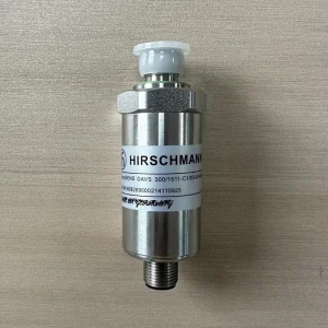
The Hirschmann DAVC 300/2511 hydraulic transducer page gives a concrete replacement candidate. It identifies a 0–300 bar measuring range, typical accuracy of ±0.15% FS and maximum accuracy of ±0.25% FS, CANopen output through a five-pin connector and a G1/4 A pressure connection. It also describes reverse-polarity and output short-circuit protection.
These specifications should be treated as the product-page scope and verified for the exact offered unit. They do not prove compatibility with every XCMG, Zoomlion or Sany crane. The buyer still needs to confirm the original part number, application, network configuration, pin assignment, hydraulic port, installation envelope and any required software mapping.
Accuracy of the transducer is not the same as accuracy of the full crane indication or safety function. The complete chain includes installation, wiring, network transmission, controller scaling, display and system validation.
What Replacement Evidence Should Buyers Request?
- Exact model and identity of the offered transducer.
- Pressure range and accuracy statement with defined conditions.
- Process-connection and dimensional information.
- Connector, pinout and electrical requirements.
- CANopen configuration or integration status.
- Declared protection functions and environmental limits.
- Inspection, test and traceability documents included with the order.
- Compatibility statement tied to the buyer’s crane and original part data.
A generic statement that the sensor “fits cranes” is not enough. Evidence should connect the offered model to the actual interface and application.
What Common Mistakes Create Procurement Risk?
- Calling the sensor a controller: the supplier receives the wrong functional description.
- Matching only 0–300 bar: port, connector and signal configuration remain unchecked.
- Assuming all five-pin plugs match: keying or pin assignments may differ.
- Treating CANopen as plug-and-play: node and application mapping are ignored.
- Skipping fault isolation: a harness or controller fault is mistaken for sensor failure.
- Using brand compatibility as proof: the exact crane, system and part number are not confirmed.
What Should the Final Hydraulic Transducer RFQ Include?
- Crane brand, model, serial details and operating function.
- Original transducer brand, model and complete part number.
- Nameplate, connector, port and installation photographs.
- Hydraulic circuit and measurement point.
- Required pressure range and known operating conditions.
- Thread, sealing and dimensional requirements.
- Connector and pinout information.
- Signal protocol, CANopen configuration and controller details.
- Fault codes, observed readings and diagnostic work.
- Environmental and installation conditions.
- Test, traceability and document requirements.
- Sample, quantity, destination and delivery requirement.
Submit these inputs through the Jiemanda replacement-parts request form. Require a response marked Confirmed, Deviation, Alternative or Buyer Input Required for each interface. This keeps the transducer’s measurement role separate from the controller while still validating the complete hydraulic-control input path.
Frequently Asked Questions
Is a hydraulic pressure transducer the same as a crane controller?
No. The transducer measures pressure and supplies a signal. The controller interprets inputs and executes programmed logic or commands.
Can any 0–300 bar CANopen sensor replace the DAVC 300/2511?
No. Range and protocol are only part of the match. Confirm the port, connector, pinout, network configuration, dimensions, application and system mapping.
Why does the original part number matter?
It helps identify the intended hardware and configuration. Similar-looking sensors may use different interfaces or ranges.
What should buyers test after installation?
Follow the crane service and safety procedure. Verify plausible pressure readings, communication, scaling, fault response and any related display or control function before return to service.
Feature Product
-
 Zoomlion Original Power Control Board – ...
🔹 Core Functions Multi-circuit Power Distrib...
-
 XCMG HC3900 Crane Upper Computer Mainboard
Key Selling Points OEM Direct Compatibility ...
-
 Zoomlion Mobile Crane Load Moment Indicator (LM...
Product Overview This is an original equipment...